
Guidance
Tolerances, printing rules, hardware sizes, and how to document your prints. Keep this page open while you're in Onshape and at the printer.
The one idea
Every one of Brown's 507 movements does the same job: motion goes in as one kind and comes out as another. A crank turns, a slider moves back and forth. A handle spins, a wheel clicks forward one tooth at a time.
Brown drew these for brass and cast iron, made by machinists. You're making them out of plastic squeezed through a hot nozzle, which is far less precise. Most of this project is learning to design around that.
Reading Brown's drawing
The drawings have no dimensions, and the descriptions are one or two sentences of 1868 English. Before you sketch, pull these out of the drawing and write them down:
- The input. What does a person turn, push, or pull?
- The output. What moves as a result, and which of the four kinds of motion is it?
- The frame. The part that never moves. Everything else is mounted to it.
- Every moving part, and exactly what each one touches. Every contact is a place you'll need a clearance.
- The trick. Most movements have one clever detail that makes them work. In the mangle rack, the gear always turns the same direction — but it can shift sideways at the ends, so it walks around the end of the rack and starts driving the other side. That's what makes the rack reverse.
The five questions your research must answer
Your research report is built around these. Answer each one in writing, and note where you found the answer.
- How does this movement work mechanically?
- What are the key components, and what does each one do?
- Which tolerances will be critical for 3D printing it?
- Which parts might need hardware reinforcement?
- What existing examples can inform your design? (Look on Printables — then design your own.)
Then sketch it by hand, with dimensions. Every part, every critical size, and a view that shows how the parts stack together. The sketch is where you catch the mistakes that cost you a two-hour print later.
Clearance: the gap that lets it move
If you draw a 5 mm pin and a 5 mm hole, they will not go together. Printed holes come out smaller than you drew them, printed pins come out a little fat, and two parts that are exactly the same size have zero room to move. Anywhere two parts slide or turn against each other, you design in a gap on purpose. That gap is the clearance.
hole Ø = pin Ø + clearance
Clearance is a total, not per side. Set it as an Onshape variable (for example #clr = 0.3 mm) and use the variable in every hole. When your first print binds, you change one number instead of twenty dimensions.
Starting clearances
These are where to start on our printers with PLA — not the answer. Your printer, your filament, and which way the part is lying on the bed all change them. Finding your real numbers is part of research question 3.
| Fit | Where you'd use it | Start at |
|---|---|---|
| Press fit | A pin that should never come out or turn | 0 to 0.1 mm |
| Snug turning fit | A gear on its axle, with no wobble | 0.2 mm |
| Free turning or sliding | A slider in a slot, a loose pivot | 0.3 to 0.4 mm |
| Flat faces rubbing | A gear riding on a base plate, a slider against a wall | 0.2 to 0.3 mm per face |
| Meshing teeth | Gear to gear, gear to rack | Move the centers 0.1 to 0.2 mm farther apart |
Print a test coupon before the real part. A small plate with a row of holes at different clearances and a matching pin takes ten minutes to print. It tells you your real numbers before you spend two hours on a part that won't go together.
Designing for the printer
The printer builds your part one layer at a time, and every layer has to sit on the one below it. That one fact explains almost every rule below.
- Put the biggest flat face on the bed. Pick the print orientation while you're designing, not after.
- Keep overhangs under 45°, or add a chamfer so they are. Support material leaves a rough face — terrible on anything that slides or turns.
- Split a part in two if that lets both halves print flat. Two parts and a screw beat one part covered in supports.
- Watch the first layer. It gets squashed a little wider than you drew — called elephant's foot. A 0.4 mm chamfer on the bottom edge of any part that fits into something else keeps it from jamming.
- Watch the seam. Every layer starts and stops at one spot, and on a round part those spots stack into a ridge up the side — the z-seam. On an axle, that ridge is a bump that catches every turn. Tell the slicer where to put the seam, or give the part a flat for the seam to sit on.
Layers are the weak direction
A printed part is strong along its layers and weak between them. Push sideways on the top of a thin peg that was printed standing up, and it snaps cleanly along one layer line — usually right at the base, where the stress is highest.
Hardware
You have M2, M3, and M4 screws, washers, nuts, and heat-set inserts. Use them anywhere a printed part would be too weak, would wear out, or needs to come apart. A screw makes a much better axle or pivot pin than printed plastic.
| Screw | Printed hole it slides through | Nut size across the flats |
|---|---|---|
| M2 | 2.4 mm | 4.0 mm |
| M3 | 3.4 mm | 5.5 mm |
| M4 | 4.5 mm | 7.0 mm |
The M number is the screw's outside diameter in millimeters. To trap a nut in a printed hexagon pocket, add about 0.3 mm to the across-flats size so it drops in.
- Heat-set inserts give you real metal threads in plastic. Size the hole from the insert's packaging, not a guess, and press them in with the soldering iron — which means you need the soldering iron quiz first.
- A washer between two parts that turn against each other cuts the friction and stops the screw head from digging in.
- Don't tighten a pivot screw down on the moving part. Clamp it to the frame, and let the moving part spin on the smooth shaft with clearance.
- Superglue is permanent. Dry-fit and run the whole movement before you glue anything. A bead of glue that squeezes out and dries can jam a sliding part for good.
In Onshape
- Attach your document to the 507 Movements assignment using Onshape's Class feature. Do this on day one, not the night before it's due.
- Model from your sketch. The dimensions on paper become the dimensions in the part studio.
- Put your clearance in a variable and use it everywhere two parts meet.
- Name parts with a version number —
gear_v1,gear_v2. When your iteration record says "v3 fixed the binding," the part name has to prove it. - Assemble with mates. Fasten the frame, then use revolute mates for parts that turn and slider mates for parts that slide. Onshape's gear and rack-and-pinion relations link moving parts together.
- Animate the assembly for your presentation — right-click a mate and choose Animate, and screen-record it.
- Export each part as STL in millimeters, one file per part, named with its version.
Documenting every print
Your first print will not work. Neither will your second, probably. That's not failing the project — that is the project. The iteration record is how you prove you fixed things on purpose instead of by luck.
For every prototype, record:
- A photo of the printed parts, and of the movement assembled.
- What went wrong, as specifically as you can. "It sticks" is a start. "It sticks at the same spot every turn, where tooth 3 meets the rack" is useful.
- Your guess at the cause. Written down before you fix it — even if you turn out to be wrong.
- What you changed, with the numbers. Hole went from 3.6 to 3.8 mm. One change per print when you can manage it.
- Print settings: layer height, infill, walls, supports, and which way the part lay on the bed.
- Assembly notes: the order the parts go together, and anything that took a trick.
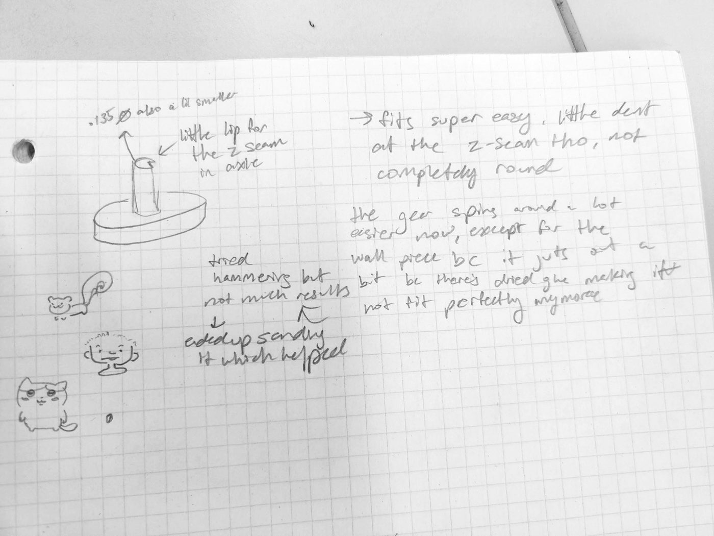
What that looked like for movement 197
A previous student's record for the mangle rack, straight from their notebook. After the first round of sketches, they redrew the whole design with new dimensions before modeling it — and drew how it would stack together.
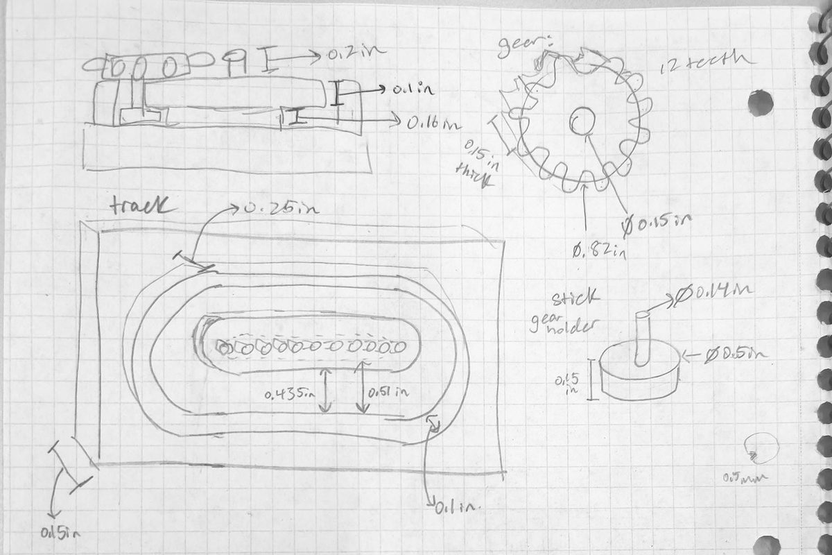
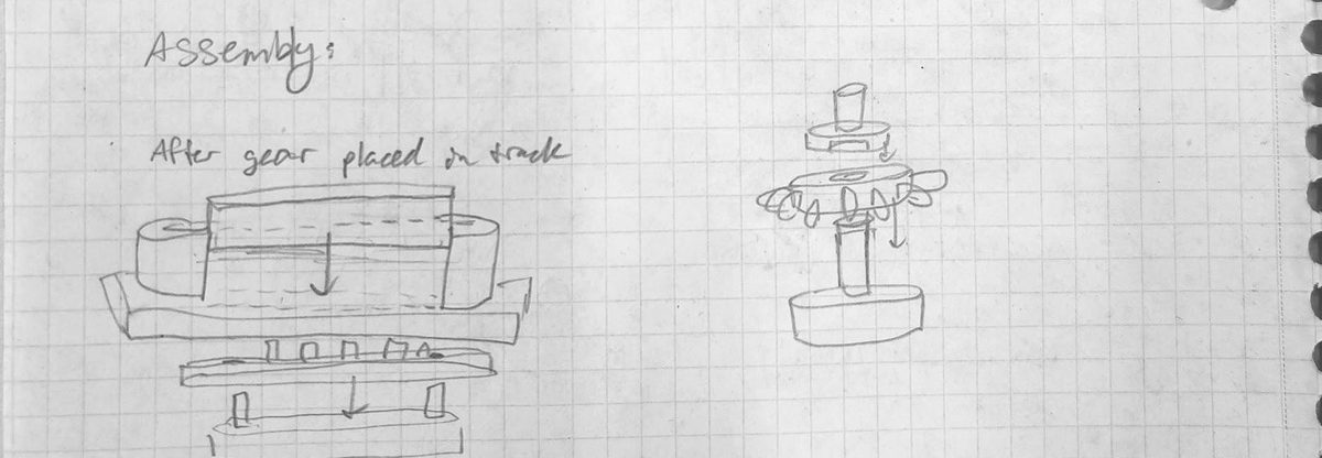
First print. Two of the standing pegs snapped off. The axle and gear fit well. The top was superglued to the base by eye, slightly off from where it should be. It ran, but the gear sometimes stuck — the notes guess it's the teeth and pegs not meshing well, or the z-seam.
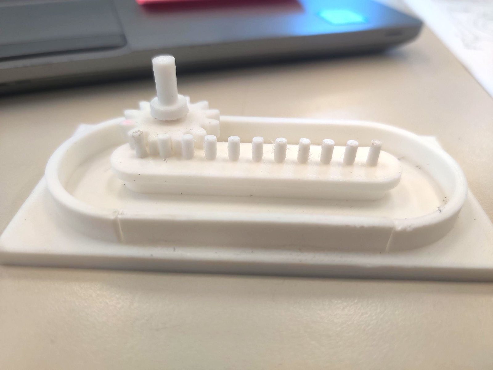
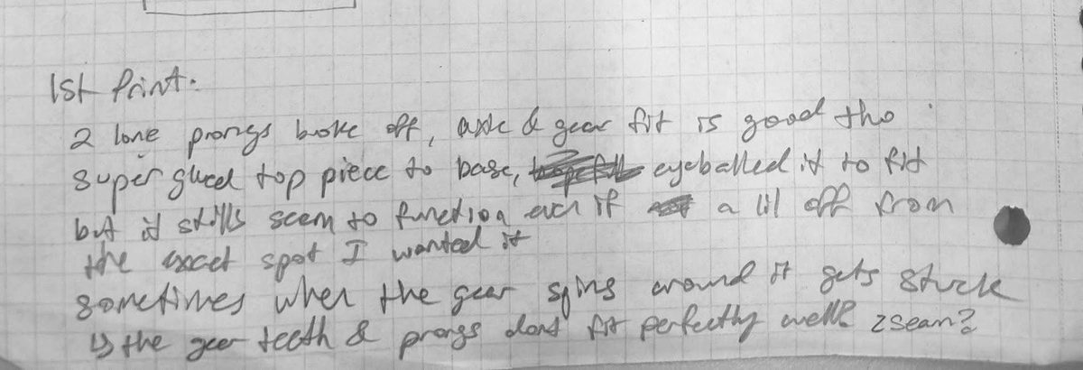
Second print. The axle was made slightly smaller, with a small lip added for the z-seam. It fit easily, though the seam still left a dent and the axle wasn't perfectly round. The gear turned much more freely — except at the wall piece, where dried glue made it stick out. Tapping it into place didn't help. Sanding did.
What's good here, and what's missing
Good: honest notes about what broke, a real number for the change, and a guess at the cause written down before it was confirmed. Every problem on this page — snapped pegs, the z-seam, glue squeeze-out — is covered above, and now you know about them before your first print.
Missing: the print settings, and a clear before-and-after. Adding those turns a good record into the one the rubric is looking for.
Tuning: problems you will have
It binds or sticks. Find the exact spot — turn it slowly and watch. Usually it's too little clearance, elephant's foot on a bottom edge, a z-seam bump, or support scars on a rubbing face. Fix that one spot, then test again.
It wobbles, or jumps out of mesh. Too much clearance, or a shaft that's too short to hold the part straight. Tighten the fit, make the bearing surface longer, or add a washer to take up the gap.
A part keeps breaking. Look at which way the layers run through it. Thicken it, fillet the inside corner, change the print orientation, or put a screw through it.
It won't go together. Check the order you're assembling in, and whether one part has to be inside another before a third one closes it off. That's what the assembly sketch is for.
Before you print, read Making Parts in the shop procedures. Failed prints are wasted material, and wasted material counts on your daily grading page score.