
Guidance
Design rules for 3D printing, clearances, joints that move, and how to check your constraints in Onshape. Keep this page open while you're modeling and at the printer.
The one idea
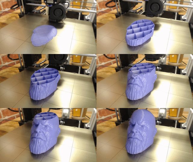
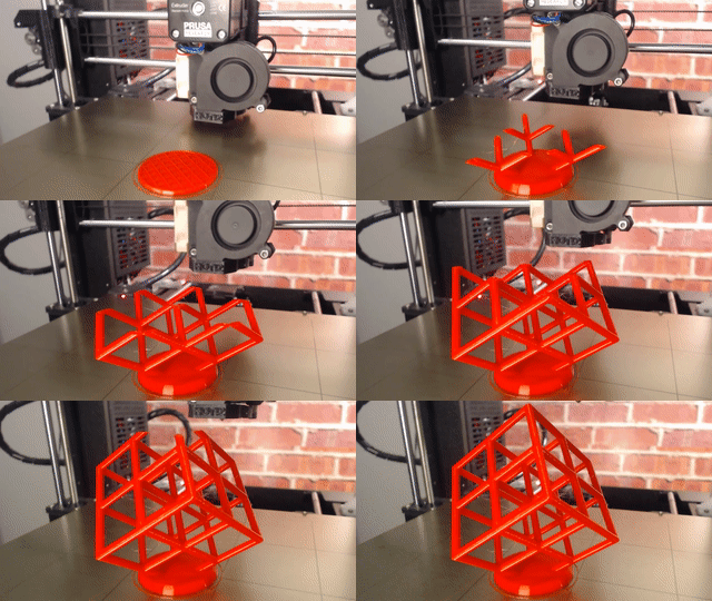
The printer builds your part one thin layer at a time, and each layer has to sit on the one below it. It's also not exact: holes come out a little small and edges come out a little fat.
Every rule on this page comes from those two facts. Design around them from the start, and your parts come off the printer and snap together. Ignore them, and you're sanding, taping, and reprinting — and the brief says none of that is allowed.
You already know the Onshape side. On the front end loader you made parts in part studios and put them together with mates. This project uses the same skills. What's new is that nobody hands you the dimensions. You decide them — and they have to work on a real printer.
The design process
Same six steps as every project in this class. This page is in the same order.
- Define the problem. Read the brief. In your notebook, write the problem, your goal, and every constraint in your own words.
- Research and brainstorm. Look at real toys, then sketch lots of ideas. See what to research and the design questions.
- Pick a solution. Compare your best ideas with a decision matrix, not a gut feeling.
- Prototype. Model it in Onshape using the design rules, then print it.
- Test and evaluate. Find what fails, fix it, and record it. See documenting every print.
- Communicate. Present your toy and your process. See how it's scored.
What to research
Take notes in your design notebook. For each thing you look up, write one line on what it means for your toy.
- Toys that move. Find three. How does each moving part attach? What keeps a wheel on, or lets an arm turn but not fall off?
- Snap-together and print-in-place toys on Printables. Study how the joints work — then design your own.
- The design rules below, and the Hydra Research design rules they come from.
- PLA vs. TPU. What each is good at, and which of your parts should be which.
- Wheels and axles on toy cars: how the wheel is held on, and what it spins on.
- Snap fits. How they flex, and why the direction of the layers decides whether they break.
- Your customer. How old are they? What makes a toy fun to play with? What makes it unsafe — small parts, sharp edges, pinch points?
The questions your sketches must answer
Sketch lots of different toys first — not the same car five times. Cross off anything that breaks a constraint, and write down why. Then sketch your best one or two in more detail. By the end, your sketches should answer every one of these:
- What is the toy, and who is it for?
- What moves, and what makes it move — a push, a roll, a hand?
- How does each moving part attach? What's the clearance at each joint?
- How does it break into parts that each print flat, with little or no support? Which face of each part goes on the bed?
- Does it fit in the 6 × 4 × 4 in box? Draw the box around it.
- About how much will it weigh? Is that under 100 g?
- Which parts are PLA, which are TPU, and why?
- If one part breaks, can it be reprinted without reprinting the rest?
Pick a solution: the decision matrix
Take your best two or three ideas. First, cross off any that break a constraint — those aren't options. Then score the rest from 1 to 5 on each thing that matters, multiply by its weight, and add it up. Agree on the weights as a team before you score.
| Criterion | Weight | Race car | Robot dog | Dragon |
|---|---|---|---|---|
| Fits the box and the budget | must pass | yes | yes | no — wings too wide |
| Fun to play with | × 3 | 4 → 12 | 5 → 15 | — |
| Prints with few or no supports | × 2 | 5 → 10 | 3 → 6 | — |
| Joints we know how to make | × 2 | 5 → 10 | 3 → 6 | — |
| Done in two weeks | × 2 | 4 → 8 | 2 → 4 | — |
| Total | 40 | 31 | out |
An example, not the answer. Pick your own criteria and weights. The robot dog was the most fun idea, but the race car won because the team could actually finish it. Write that reason in your notebook — it's the kind of decision the rubric asks you to explain.
Design rules at a glance
These numbers are from the Hydra Research design rules for FFF printing — the kind of printer in our shop. They're starting points, not guarantees. Each one is explained below.
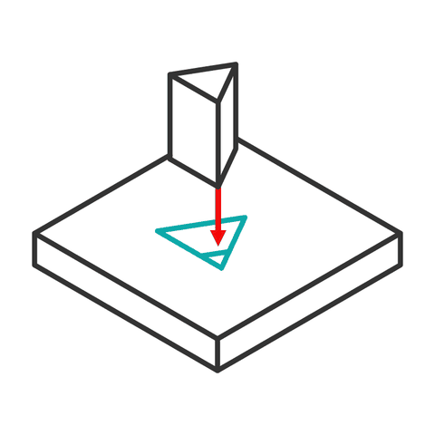
0.2 mm loose · 0.1 mm tight
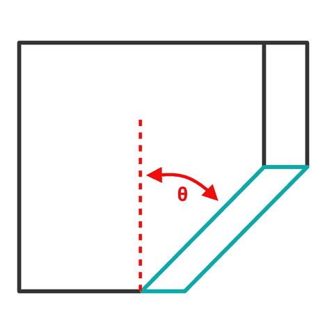
under 50° from vertical
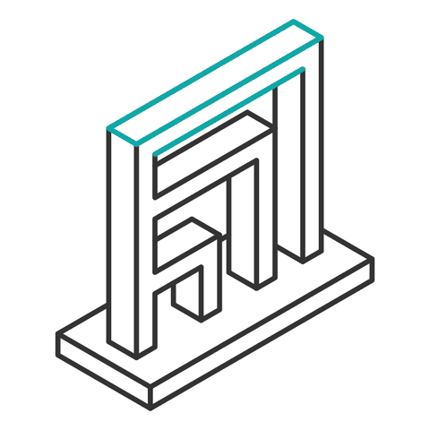
under 10 mm long
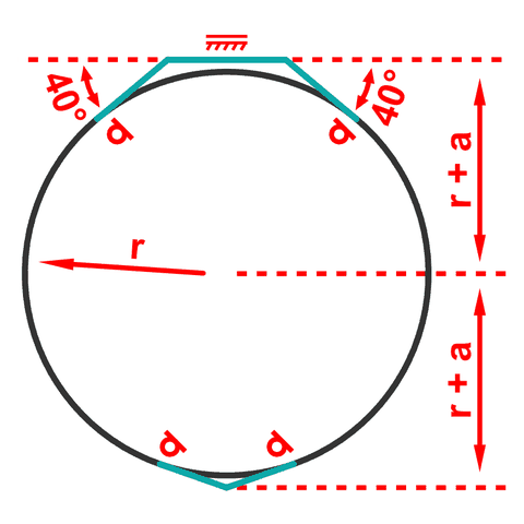
add a small flat top and bottom
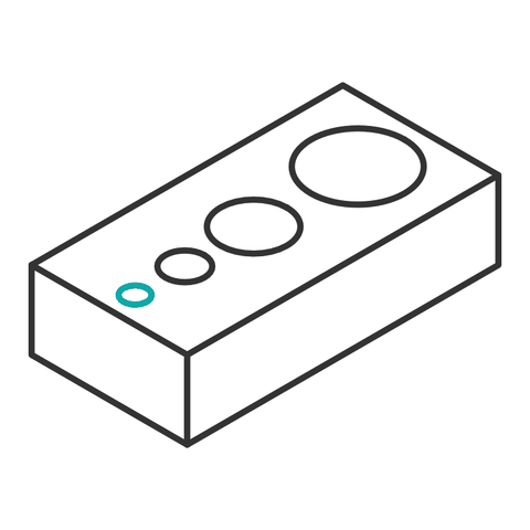
at least 2 mm across
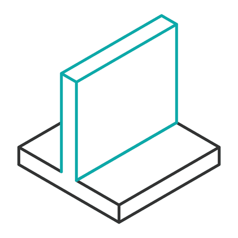
at least 0.9 mm thick

at least 1.8 mm
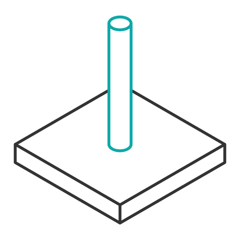
at least 1.8 mm across
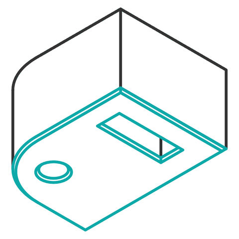
about 0.3 mm on edges touching the bed
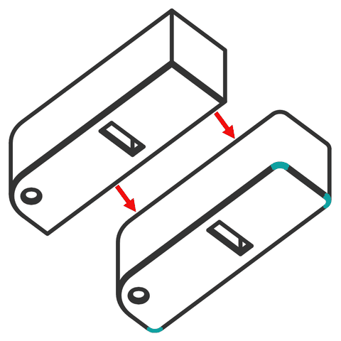
round them, R 4 mm or more, on big parts
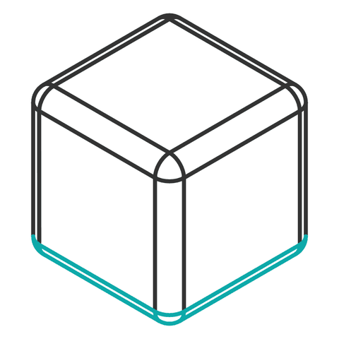
at least 1 mm; not on downward-facing edges
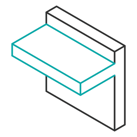
unsupported ledges under 0.9 mm
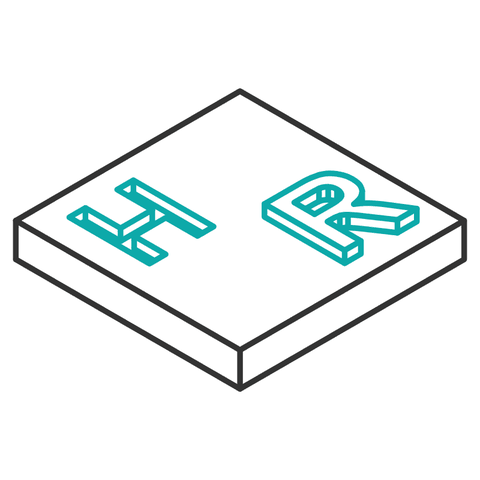
lines 0.9 mm wide raised, 0.5 mm engraved

up to 2 mm out or in

hole = 96% of the screw's diameter
Illustrations: Hydra Research, CC BY-SA 4.0. Tap a rule name to jump to the explanation.
Working in inches? Onshape takes any unit in any box. Type 0.2 mm into a dimension in an inch document and it converts it for you. For reference: 0.1 mm ≈ 0.004 in, 0.2 mm ≈ 0.008 in, 1 mm ≈ 0.04 in, 10 mm ≈ 0.39 in.
Clearance: the gap that makes it move
Draw a 5 mm pin and a 5 mm hole, and they won't go together. Printed holes come out small, printed pins come out fat, and two parts the same size have zero room to move. Anywhere two parts touch, you design in a gap on purpose. That gap is the clearance.
hole Ø = pin Ø + clearance
Start at 0.2 mm for anything that moves and 0.1 mm for anything that shouldn't, then check them on the Tolerance Blocks. Clearance is a total, not per side. A 5 mm axle that needs to spin gets a 5.2 mm hole.
Which fit goes where on a toy
| Joint | Fit | Start at |
|---|---|---|
| Wheel spinning on its axle | Loose | 0.2 mm |
| Axle held in the body so it can't turn or slide out | Tight | 0.1 mm |
| Arm, leg, or head that turns on a peg | Loose | 0.2 mm |
| Two flat faces that rub, like a wheel beside the body | Loose | 0.2 mm or more between the faces |
| Part that slots into another and stays | Tight | 0.1 mm |
- Put your clearance in a variable. In Onshape, add a Variable feature:
#clr = 0.2 mm. Then size every hole as something like5 mm + #clr. When your first print is too tight, you change one number instead of twenty.
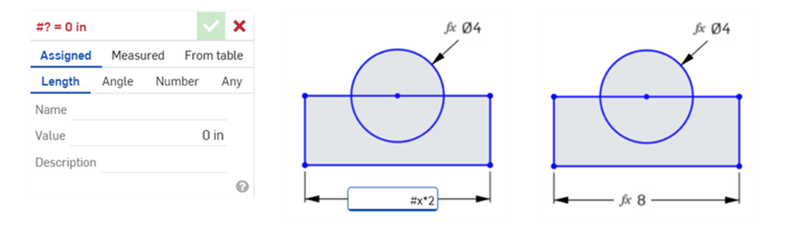
clr, value 0.2 mm. Middle: type the variable into any dimension with a #. Right: Onshape does the math. Change #clr once and every hole updates. (Images: Onshape Help.)Find your real number: the Tolerance Blocks
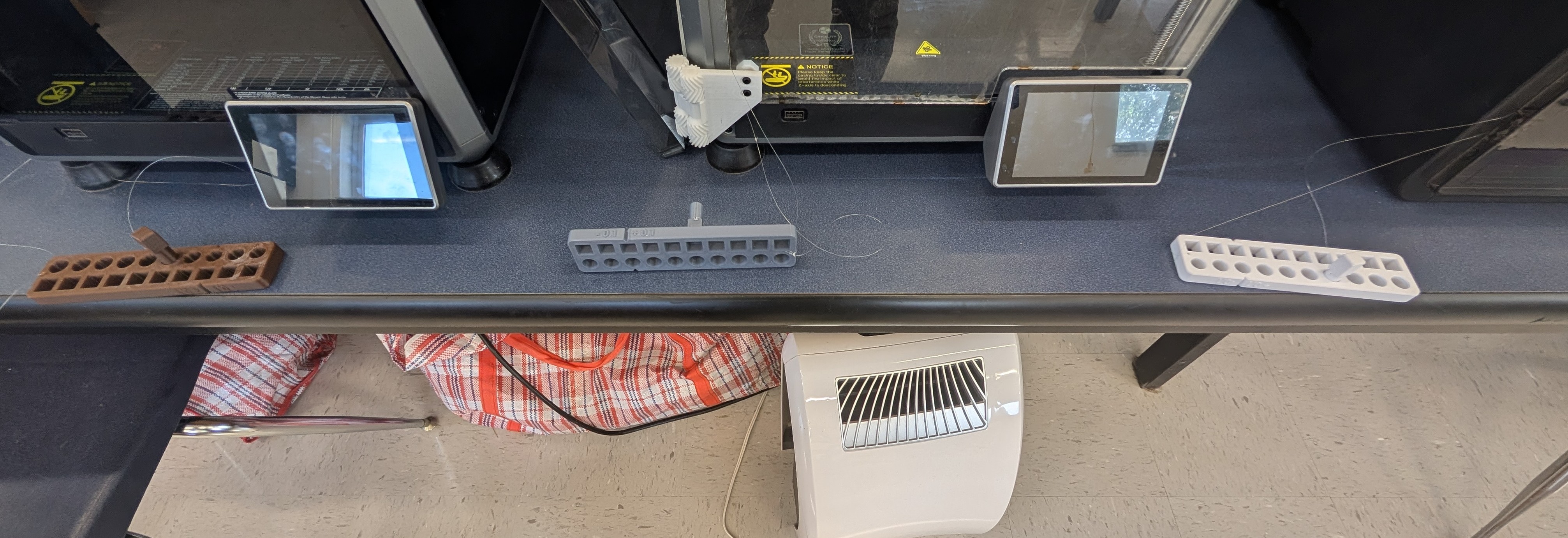
0.1 and 0.2 mm are starting points. Every printer is a little different. Each of our three printers has its own set of 3D Printer Tolerance Blocks next to it — test pieces printed on that printer, with the same pin in holes at different clearances.
- Decide which printer you'll use for your toy, and go to its blocks.
- Try each fit by hand. Find the clearance that feels right for each joint: one that holds still, one that turns freely.
- Write it down: the printer and the clearance for each kind of fit. Then set
#clrto that number. - Print on that same printer. A number from one printer doesn't promise the same fit on another.
- Still not sure? Print just the joint — a few minutes and a gram or two — before you print the whole part.
Overhangs and bridges
Each layer has to sit on the one below. A wall can lean a little, because each layer still mostly rests on the last one. Lean it too far and the new layer is printing on air — it droops and curls. Angles are measured from straight up.
A bridge is a flat span between two supports. The printer can stretch plastic across a short gap like a string. A long one sags.
- Pick the print orientation while you design, not after. Put the biggest flat face on the bed.
- Avoid supports on anything that moves. Support material leaves a rough face — terrible for a wheel hub or a pivot.
- Split a part if that lets both halves print flat. Two parts that snap together beat one part covered in supports. It also helps with the modular rule.
- Turn a steep overhang into a chamfer. A 45° slope under a ledge prints clean where a flat ledge would droop. Put a slope under anything that sticks out — a tab, a hinge, a pin mount — so it has something to build up from. See the snake car.
- Give round parts a flat side. See below.
Round parts need a flat side
A round part lying on the bed touches it along one thin line. It wobbles, it doesn't stick, and the whole bottom half is an overhang that needs support. Slice a little off the bottom and it sits flat. Cut off the bottom fifth of the diameter and the steepest overhang left is about 37° — under the 50° limit, so it prints with no support at all.
Holes
Holes going straight up (the axis points at the ceiling while printing) come out a little small and slightly faceted. Your clearance takes care of that.
Holes going sideways are trickier. The top of a round hole is a flat overhang — right at the top it's 90° — so it droops. On a wheel or an axle hole, that droop is a bump that catches every turn.
Smallest hole: 2 mm. Anything smaller may close up. If you need a small hole to be exact, print it a little undersize and drill it to size.
A hole that starts in mid-air
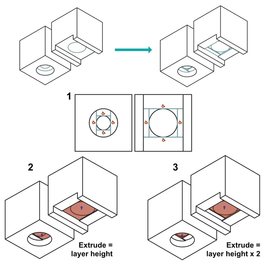
A small hole at the bottom of a wider pocket — like a screw hole under a counterbore — has nothing to print its first layer on. Hydra's fix: at the step, extrude two thin rectangles that just touch the hole. The first is one layer tall. The second, turned 90°, is two layers tall. The printer bridges each one cleanly, and the hole comes out square-edged but open. Or just flip the part over.
Thin walls, pins, and small features
The nozzle lays down a bead of plastic about 0.45 mm wide. That's the smallest thing the printer can draw. Everything you make is built from those beads side by side.
wall ≥ 2 × bead · feature ≥ 4 × bead
With a 0.45 mm bead: walls at least 0.9 mm, pins and small features at least 1.8 mm. These are the smallest the printer can make — not the smallest a toy can survive.
A toy gets dropped, stepped on, and chewed. Treat the minimums as a floor. A wall a kid will squeeze wants 1.5–2 mm. An axle that carries the weight of the toy wants 3 mm or more — or a dowel or rod you don't print at all.
Edges: chamfers and fillets
The first layer gets squished onto the bed so it sticks. That squish spreads it a little wider than you drew — a lip called elephant's foot. On a part that slides into another one, that lip jams the fit. A tiny chamfer on every bottom edge fixes it.
Fillets (rounded edges) look great and make a toy safer to hold. But a fillet on the underside of a ledge starts out perfectly flat — a 90° overhang — so it droops. Use a 45° chamfer there instead.
- Base chamfer: about 0.3 mm on every edge that touches the bed, especially on parts that slide into something.
- Fillets: at least 1 mm, or they're too small to print. Use them on corners a hand will touch.
- Round the base corners of big, flat parts — radius 4 mm or more. Sharp corners are where a part peels up off the bed (warping).
- No wide ledges sticking out in mid-air. An unsupported flat ledge wider than 0.9 mm prints messy underneath. Chamfer it, or turn the part.
- Inside corners on a peg or a snap arm: a fillet at the root spreads the stress so it doesn't crack there.
Text and surface details
A logo, a name on the side of a car, the cross on a shield — details make a toy. Keep them big enough to print.
- Raised letters and lines: at least 0.9 mm wide.
- Engraved (cut-in) letters and lines: at least 0.5 mm wide.
- How far out or in: on a side wall, up to about 2 mm. On a top face, keep it under 0.9 mm — a few layers is plenty.
- Text prints best on a top face. On a side wall, every letter is built from stacked layer edges and looks rough. Choose a bold, simple font.
Layers are the weak direction
A printed part is strong along its layers and weak between them. Push sideways on a thin peg that printed standing up, and it snaps cleanly along one layer line — usually at the root, where the stress is highest. The same peg printed lying down is several times stronger, because now the layers run the length of it.
Joints for a toy that moves
The brief says no tape and no sanding. So every connection is a joint you designed in CAD. Here are three that work well for printed toys. Mix and match.
Wheel on an axle
- One end tight, the turning end loose. Either the axle is fixed in the body and the wheel spins on it, or the axle is fixed in the wheels and spins in the body. Not both loose — it'll wobble.
- Keep the wheel on with a cap, a collar, or a snap on the axle end. Friction alone won't hold it.
- Leave a gap between the wheel and the body so their flat faces don't rub.
- Make the hub long. A wheel that rides on a longer stretch of axle wobbles less.
- A wooden dowel or metal rod is stronger and smoother than a printed axle. See parts you don't print.
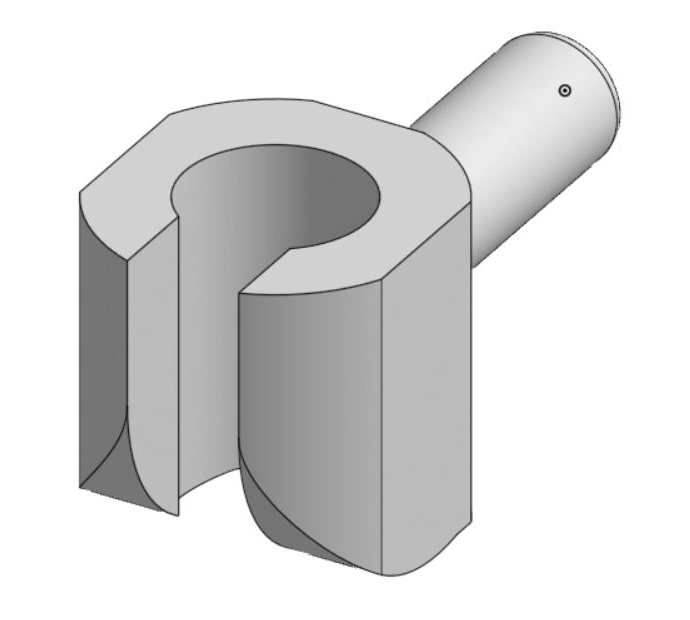
C-clip snap
- Make the opening a little narrower than the rod — start about 15–20% narrower — so the arms flex open and snap back.
- Inside the C, use your loose clearance if the rod should turn, tight if it shouldn't.
- Print it so the layers run around the C, not across the arms. Otherwise the arms snap off the first time.
Split snap pin
- The barbs stick out wider than the hole. The slot has to be wide enough that the two halves can squeeze to the hole size.
- Print the pin lying on its side so the layers run the length of the prongs.
- Use it where a part should come off again. Pull the barbs together and it slides back out — that's your modular, replaceable part.
TPU: the flexible one
TPU is rubbery. It bends, grips, and bounces back. Use it where PLA would crack or slip — and nowhere else.
- Tires. A TPU tire on a PLA wheel grips the floor and rolls quietly. Make the tire's inside diameter a little smaller than the rim — start about 1 mm smaller — so it stretches on and stays put. A groove in the rim keeps it from walking off.
- Bumpers, grips, and bendy bits. A tail that wags, an antenna that bends, a soft nose.
- Not for precise holes. TPU squishes, so tight clearances don't mean much. Put your pivots and axle holes in PLA.
- Thin bends, thick doesn't. A 1 mm TPU strip flexes. A 5 mm block of it is nearly stiff.
- TPU prints slowly and needs different settings. Check with Mr. Hubbard before you send one to the printer.

Parts you don't print
Not every part has to come off the printer. Wooden dowels, screws, washers, and other parts we already have in the shop are often stronger, smoother, and faster than anything you could print. Hydra's own advice on pins: if a pin has to work hard, use a real one and model holes for it on both sides.
Ask Mr. Hubbard what's in stock before you design around it. Then design your printed parts to fit the real thing.
Wooden dowels
A long, thin printed cylinder is about the hardest thing to print well. Lying down, it's round on the bed with nothing holding it. Standing up, every layer is a weak spot, and it snaps. A wooden dowel is straight, round, strong, and free. That's why the snake car uses one for its axle.
- Measure the real dowel with calipers. A "¼-inch" dowel is rarely exactly 0.250 in, and it isn't perfectly round. Measure in a few spots and use the biggest number.
- Holes it spins in: measured diameter + your loose clearance. Wood is rougher than printed plastic, so you may want a little more — check on the Tolerance Blocks.
- Holes that grip it, like a wheel hub: measured diameter + your tight clearance, or a hair smaller for a press fit. A long hub grips better than a thin one.
- Cut it to length with the right tool, and only after you've passed that tool's quiz on Machine Quizzes. Sand the cut end so it doesn't splinter.
Screws, nuts, and washers
- Self-tapping into plastic: make the hole 96% of the screw's diameter (measure the threads with calipers). The screw cuts its own threads. Drive it in once, slowly — every time you take it out and put it back, the threads get weaker.
- A pivot: the moving part gets a clearance hole and turns on the smooth part of the screw. Only the fixed part is threaded. Never tighten a screw down on the part that's supposed to move.
- Washers between two parts that rub cut the friction and stop the screw head from digging in.
- Don't model threads for screws smaller than M5 (#10). They won't print well enough to hold.
- Heat-set inserts give you real metal threads. Make the hole 98% of the insert's outside diameter. You'll press them in with the soldering iron, so you need the soldering iron quiz first.
Designing around them in Onshape
- Model every bought part as a simple part — a dowel is just a cylinder — and name it so it's obvious, like
dowel_6mm (not printed). Your assembly isn't complete without it, and the box check needs it. - Screws, nuts, and washers are already in Onshape. In an assembly, use Insert → Standard content.
- Don't export them as STLs. Only printed parts go to the slicer.
- The rules still apply. Bought parts must stay in by design — a press fit, a cap, a snap, a screw. No tape, no glue holding them in.
- The budget: the 100 g counts PLA and TPU. Bought parts aren't printed, so they're not in it — but they still have to fit in the box.
Break it into modules
One giant part is hard to print, impossible to fix, and wasteful when it fails. Split the toy into smaller parts that each print flat and connect with the joints above.
- Each part has one job and one best side to lie on.
- Every connection comes apart. If a wheel breaks, the store reprints the wheel. Glue makes a part impossible to replace.
- Mirror, don't redraw. Left and right arms, or four identical wheels, come from one design.
- Test the hard parts first. Print just the joint before you print the part it's on.
Checking the constraints in Onshape
Check the box and the budget in CAD, before anything touches the printer. It's the cheapest place to find out you're too big.
6 × 4 × 4 in ≈ 152 × 102 × 102 mm
Model a box this size in its own part studio and insert it into your assembly. Make it see-through by lowering its opacity in the part's appearance. If anything pokes out — a sword tip, a spoiler, a wheel — you're too big. Don't print the box.
printed mass ≈ volume × 0.6 g/cm³
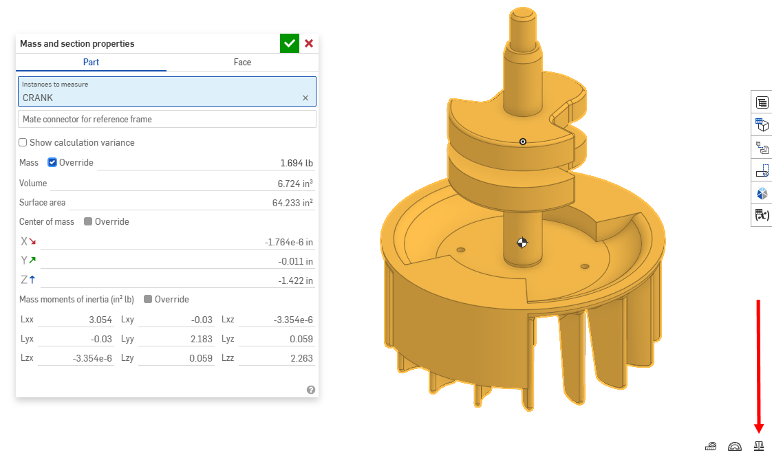
Solid PLA is 1.24 g/cm³, but your parts aren't solid. We print at 15–20% infill: the outside walls and the top and bottom layers are solid, and the inside is a light grid. A typical toy part comes out about half the weight of a solid one, so use 0.6 g/cm³ to estimate. Read each part's volume from the Mass properties tool in Onshape and multiply.
Document in inches? Onshape shows volume in in³. One in³ is 16.4 cm³, so a printed part weighs about 10 g per in³ (20 g per in³ for thin parts).
- Thin parts are almost solid. Anything under about 5 mm thick — a wheel, an arm, a snap — is nearly all wall. Use 1.24 g/cm³ for those.
- TPU tires usually print close to solid. TPU is about 1.21 g/cm³.
- Example: a car body with a volume of 60 cm³ is about 60 × 0.6 = 36 g. Four 3 cm³ wheels are about 4 × 3 × 1.24 ≈ 15 g. That's 51 g so far.
- The slicer has the final word. Once you slice, use its filament weight instead, and add it up for every part.
- Fully constrain every sketch. Black lines, not blue. The brief asks for it, and a sketch that isn't pinned down moves when you change something else.
- Use your
#clrvariable in every hole and every fit. - One part studio per part, or a few related parts per studio. Name the tabs.
- Assemble with mates. Fasten the body. Revolute mates for wheels and joints that turn, slider mates for things that slide. Then drag the parts through their full motion. Anything that crashes into something else needs more room.
- Turn on interference detection in the assembly. It highlights parts that overlap. Overlap means they can't both exist.
- Name parts with a version number —
wheel_v1,wheel_v2. When your notebook says "v3 fixed the wobble," the part name proves it. - Animate a mate for your presentation, and screen-record it.
- Export each part as an STL. Check the units. A 6-inch toy that shows up 6 mm tall in the slicer was exported in the wrong unit.
At the printer
- Watch the OrcaSlicer video on the Making Parts page before your first print.
- Test pieces first. Print just the joint, the axle hole, or the snap. A few grams now saves a whole part later.
- Lay each part on its best face. Big flat face down, layers along the pins, no supports on moving faces.
- Read the filament weight in the slicer for every part and write it in your notebook. Lower infill lightens a part; the outside walls do most of the work.
- Watch the seam. Every layer starts and stops at one spot. On a round part those spots stack into a ridge — a bump that catches on every turn of a wheel. Tell the slicer where to put the seam.
Two from previous years
Both are real student projects. Names are cropped out of every image.
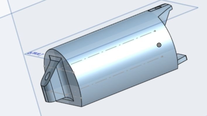
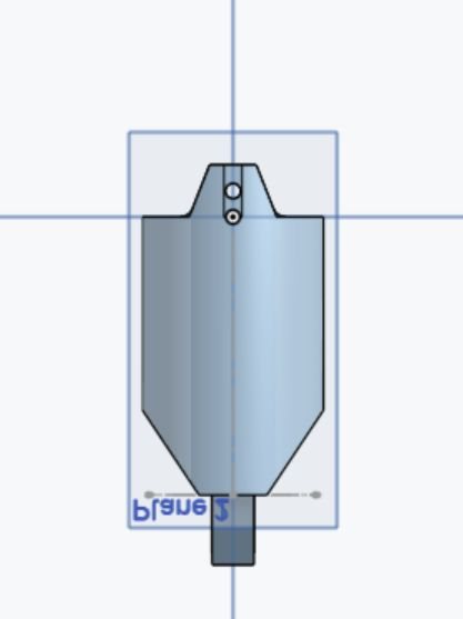
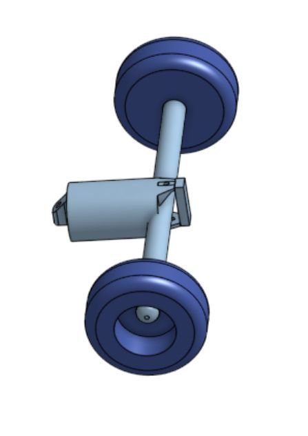
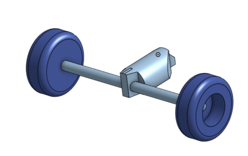
The snake car
A snake on wheels, inspired by jointed toy snakes. Each body segment pivots on the next, so the snake bends as it rolls.
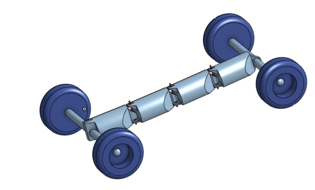
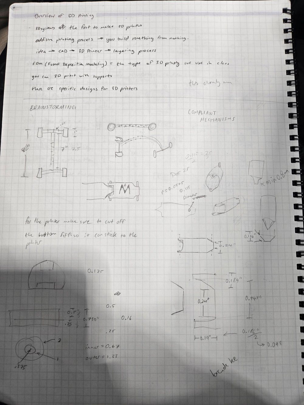
What changed after the first prints, from the student's notes:
- The bottom of a segment was too thin and printed badly. Fix: made it thicker. (That's the wall thickness rule.)
- The hole for the wire pin was too small. Fix: made it bigger so it printed cleanly. (That's clearance.)
- The axle connector was glued on. Fix: redesigned it to fit the dowel directly — stronger.
- The segments slid along the axle. Quick fix: rubber bands on the axle as stoppers.
What's good here, and what's missing
Good: every part was designed for the printer. Round parts got a flat side. Tabs got a slope underneath, so nothing needs support. The axle is a wooden dowel, and the pin is music wire, because a long thin printed cylinder would be weak. The iteration notes say what failed, why, and what changed. The reflection is honest: the snake sags in the middle, and a stiffer spine would fix it.
Missing for this brief: the build used superglue and rubber bands, and this brief allows neither. The student already named the fix — printed stop collars on the axle instead of rubber bands. Snaps or a tight fit would replace the glue. No clearance numbers are written down, and there's no weight total.
The building-block knight
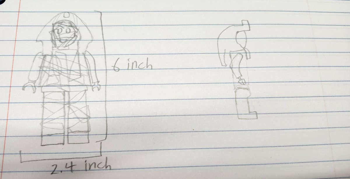
A building-block knight that moves: the head turns, the arms swing, the hands turn and grip, the legs swing. About 6 inches tall.
It started as something else. The first idea was a mummy. The pharaoh's mask turned out to be too hard to model, so the design changed to a knight. That's a real design decision — write yours down, too.
What's good here, and what's missing
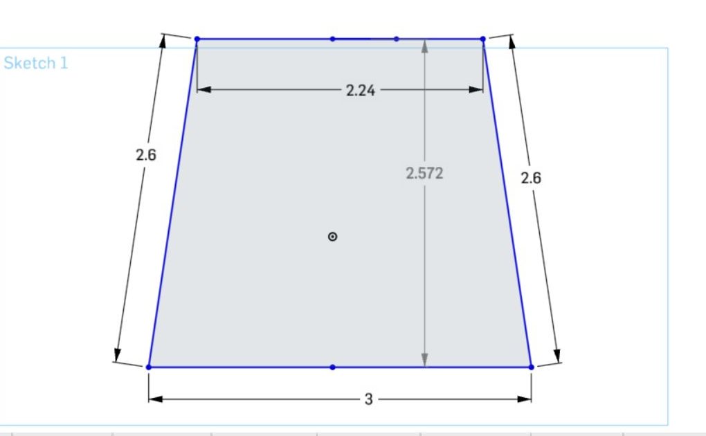
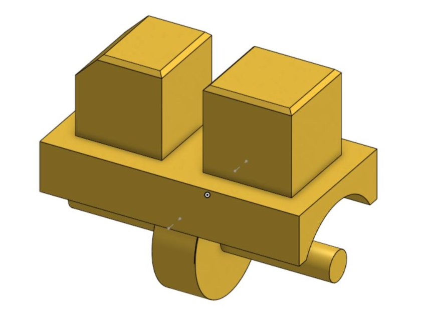
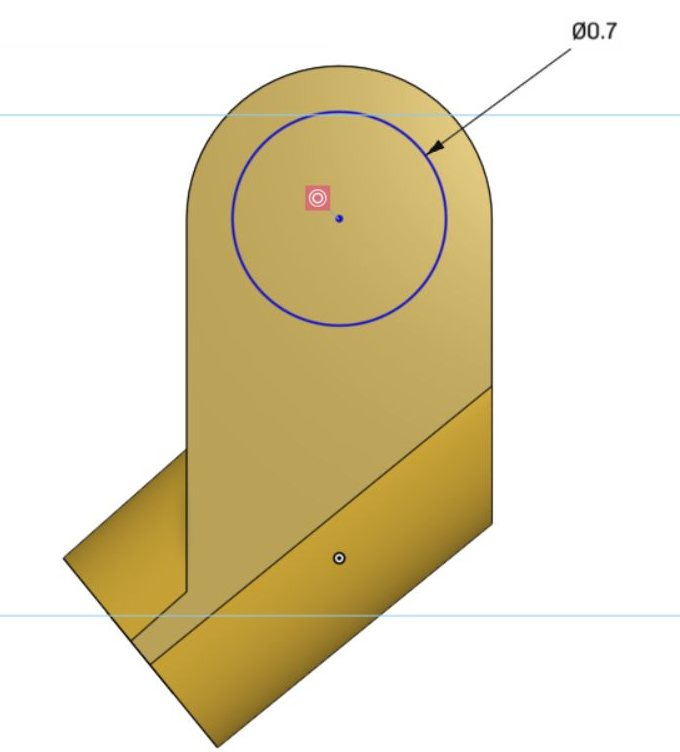
Good: the overall size was sketched before modeling. Every part has its own part studio — head, body, hip, both legs, both arms, both hands, helmet, sword, and shield — so any one can be reprinted. The sketches are fully dimensioned. And the moving parts use real joints: a pin at the hips, pegs at the shoulders and wrists, and a C-clip that grips the sword.
Missing: no clearance anywhere in the slides. If the hand's peg is also Ø0.7 in, it won't go into a Ø0.7 in hole. There's no print orientation — which face of that angled arm goes on the bed, and which way do the layers run through the wrist peg? No weight estimate. And at exactly 6 in tall, the knight has zero margin in a 6-inch box.
Also missing: test prints and iteration. The slides stop at CAD. Your notebook needs what happened at the printer — see below.
Test and evaluate: document every print
Your first print won't be perfect. That's not failing — that's the project. The notebook is how you prove you fixed things on purpose instead of by luck. For every test piece and every prototype, record:
- A photo of the printed part, and of the toy assembled.
- What went wrong, as specifically as you can. "The wheel is stiff" is a start. "The front left wheel binds once per turn, at the seam" is useful.
- Your guess at the cause, written before you fix it — even if you turn out to be wrong.
- What you changed, with the numbers.
#clrwent from 0.2 to 0.3 mm. One change at a time when you can. - Print settings: which face was on the bed, infill, supports, and the filament weight.
- A running weight total for the whole toy against the 100 g budget.
Tuning: problems you will have
It won't go together. Too little clearance, elephant's foot on a bottom edge, or a drooped sideways hole. Find the exact spot that's tight. Check that fit on the Tolerance Blocks for your printer. Raise #clr, add a base chamfer, or change the hole to a teardrop — don't sand it.
It's floppy, or parts fall off. Too much clearance, or nothing holding the part on. Tighten that fit to 0.1 mm, add a cap or a snap, or make the hub longer.
It doesn't roll straight. Axles aren't parallel, a wheel wobbles, or a wheel rubs the body. Check the assembly from the top view, lengthen the hubs, and add a gap between wheel and body.
A snap or peg keeps breaking. Look at which way the layers run through it. Turn the part, thicken it, fillet the root, or make the arm longer so it bends less sharply.
It's over budget. Lower the infill, hollow out thick parts, thin walls that are way over the minimum, or shrink the toy a little. Re-check the weight in the slicer after each change.
Before you print, read Making Parts in the shop procedures. Failed prints are wasted material, and wasted material counts on your daily grading page score.