
Guidance
What you need from class to design this container and draw it properly. Keep this page open while you draw.
The one idea
You need a one-way door with no moving parts. Blades have to get in easily. Getting back out has to be nearly impossible — no matter which way the container ends up.
With no flaps allowed, the only tool you have is shape. Think piggy bank, ballot box, or lobster trap: the way in is easy to find from outside and hard to find from inside.
The constraints, as a checklist
Every concept you sketch should pass all of these. If one fails, cross it out and say why in your notebook — that's good research, not wasted time.
- Takes all four blade sizes. The slot fits the biggest; the trap still works for the smallest.
- Blades stay in for good once they're deposited.
- Knocked over or upside down, nothing comes out.
- No instructions needed. A student walking up to it knows where the blade goes.
- One single plastic part. No lids, hinges, flaps, or moving pieces.
- Simple to make. Could you picture it coming out of one mold, or off a 3D printer?
- Reasonable size. Smaller is cheaper. It only has to hold a year of blades.
- Safe. No sharp edges or pinch points. Round the corners.
- Durable. Survives a year of classroom use.
What to research
Take notes in your engineering notebook. For each thing you look up, write one line on what it means for your design.
- The four blades: measure each one — length, width, thickness. Write the numbers down.
- How real sharps containers and blade disposal boxes keep blades in
- What plastics real sharps containers are made of, and why
- How one-piece plastic parts are made — injection molding and 3D printing — and what shapes each one can't make
- Who uses it: students, teachers, custodians. What does each of them need?
The questions your sketches must answer
Sketch at least three different concepts — not the same box three times. Each sketch should try to answer these. Draw the whole container and zoom in on the important details.
- Where does the blade go in, and how does a student know that without being told?
- How big is the opening, and does the largest blade fit?
- What stops a blade from coming back out when it's upside down? On its side?
- How big is the whole container, and how many blades will it hold?
- Where could someone get cut or pinched, and how did you design that out?
- Could it be made as one piece of plastic?
Multiview drawing
A multiview drawing shows the part straight-on from different sides. You need at least three views: front, top, and right side. The drawing sheet uses third-angle projection, so the views go in fixed places:
- Top view goes directly above the front view. Same width.
- Right side view goes directly to the right of the front view. Same height.
- The front view should be the side that shows the most about the part.
- Hidden lines show what's inside. That's how the reader sees your trap.
Line types
Isometric drawing
The isometric view is the 3D picture that helps a reader understand the other views. It goes in the fourth box on the sheet.
- Width and depth run at 30° from horizontal. Use the isometric grid.
- Vertical edges stay vertical.
- Measure only along the three axes. Slanted edges get found by connecting points.
- No hidden lines in the isometric view.
- Circles turn into ellipses.
Drawing to scale
The sheet is a 1/4-inch grid. You decide what one box stands for, then stick to it on every view. Pick a scale that makes your largest view fill most of its box without running off the edge.
boxes = real size ÷ size of one box
A container 6 inches tall at 1 box = ½ inch is 6 ÷ ½ = 12 boxes tall. Count how many boxes fit in one view panel before you choose.
size of one box ≥ largest dimension ÷ boxes available
Then round up to an easy number — ¼ in, ½ in, 1 in, or 0.5 cm. Write it in the SCALE block, like "1 box = ½ in".
Dimensions that don't fit the grid. Wall thickness, slot width, and corner radius are usually smaller than one box. Add a dimension line with the real size for each one. The reader should never have to guess a number.
Fill in the whole title block — name, object, date, and scale. Give your design a name in the OBJECT box.
Two from a previous year
Both of these are real student drawings. Names are blocked out.
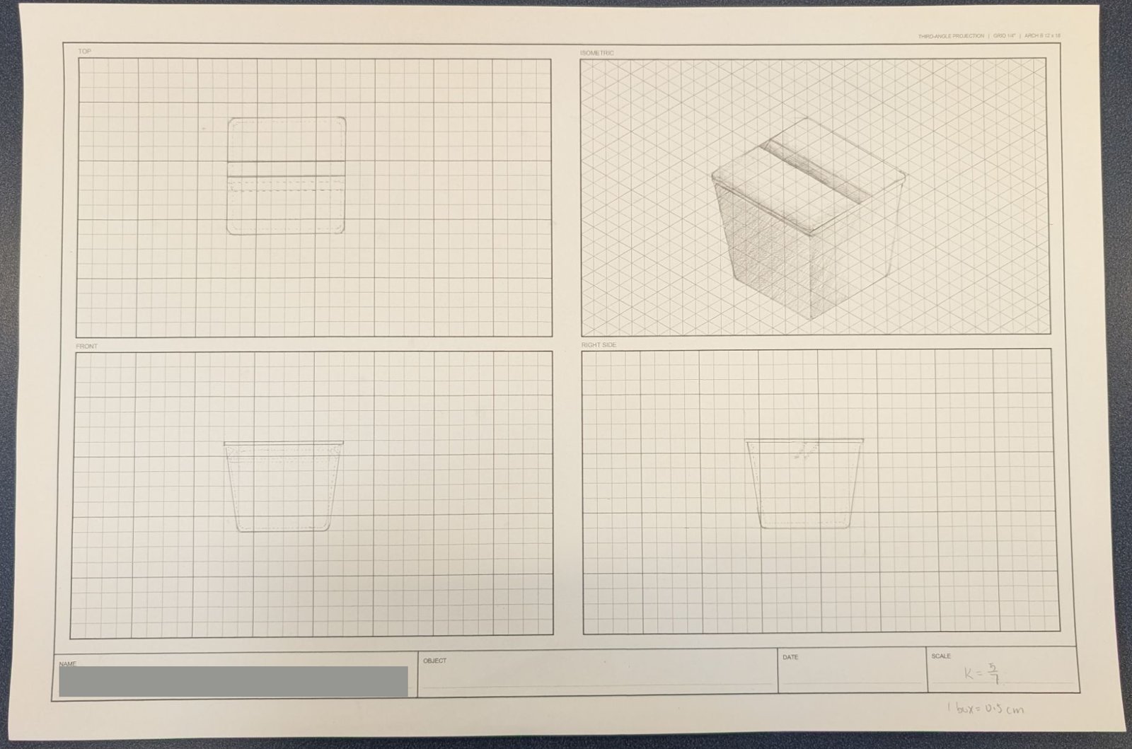
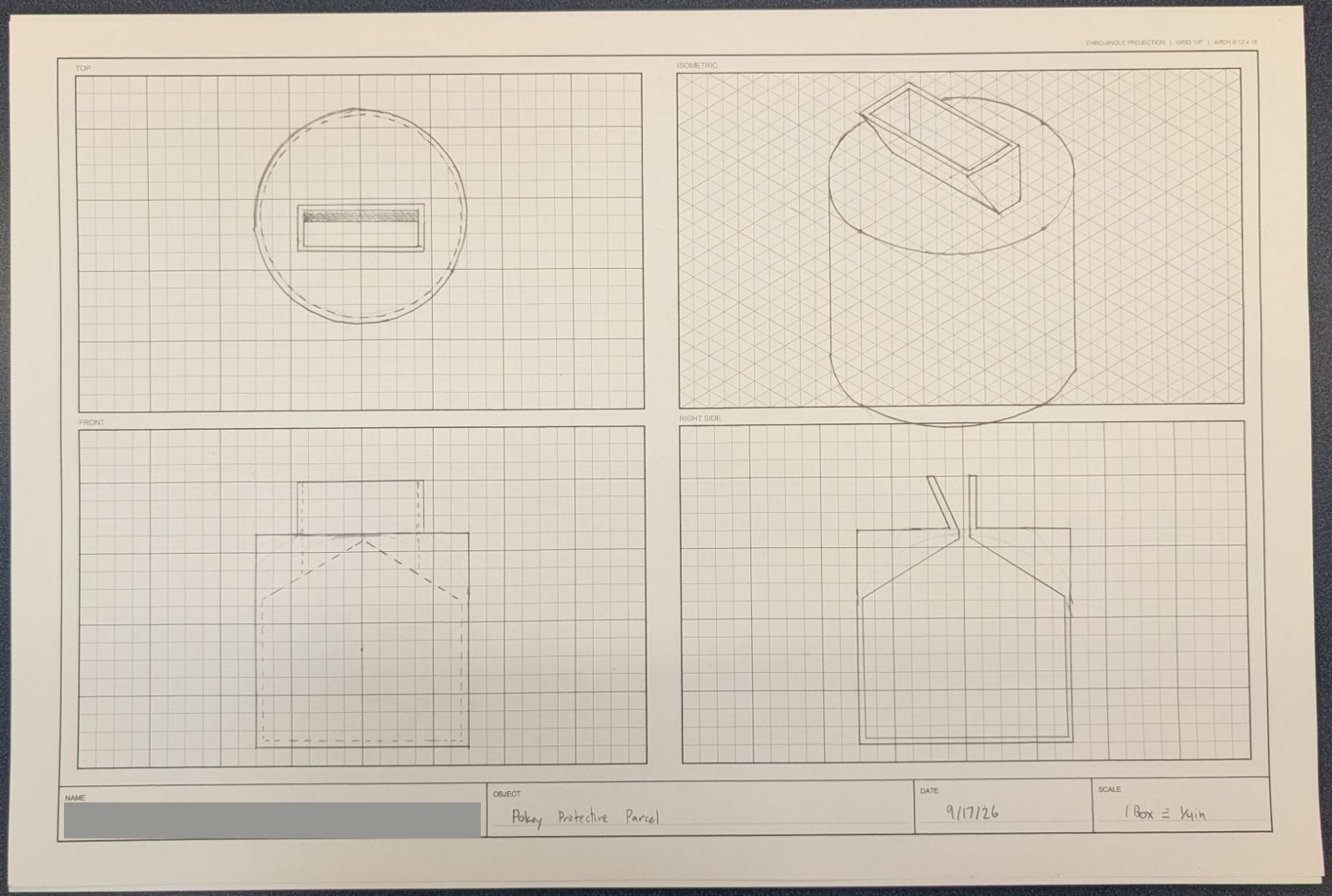
What's good here, and what's missing
The tapered box. The views line up, and the rounded corners deal with sharp edges. Hidden lines show the wall thickness. The isometric is clean and shaded well. But the drawing doesn't show what keeps a blade from falling back out through the slot when it's flipped over — and that's the whole problem. The OBJECT and DATE boxes are empty, and the scale is written outside the SCALE box.
The cylinder. The trap is easy to read: a chute leads into a funnel, and the front view shows the funnel with hidden lines. The scale ("1 box = ¼ in") and title block are complete. The miss: in the right side view, the funnel is drawn with solid lines. It's inside the part, so it should be dashed there too. The top view also needs a center mark for the circle.